MECHANICAL DRAWING. - ppt download
By A Mystery Man Writer
Last updated 19 May 2024
Why do we draw? To communicate!!! Picture is worth a 1000 words!!! words are pretty effective for some situations, often in Engineering and design, pictures are much more effective Importance of communication - what’s your idea worth if you cant share it with others In the real world you have to collaborate, so you need to know how to communicate your ideas or they are not very useful to you
words are pretty effective for some situations, often in Engineering and design, pictures are much more effective. Importance of communication. - what’s your idea worth if you cant share it with others. In the real world you have to collaborate, so you need to know how to communicate your ideas or they are not very useful to you.
No one is an expert at everything, so we must collaborate to reach a common goal. Picture is worth a 1000 words!!! words are pretty effective for some situations, often in Engineering and design, pictures are much more effective. Importance of communication. - what’s your idea worth if you cant share it with others. In the real world you have to collaborate, so you need to know how to communicate your ideas or they are not very useful to you.
Subject – what you are trying to convey (Process, structure, function, material, etc….) Audience – who you are communicating with (designer, client, manager, public, other engineers) Two important things to think about when drawing.
Drawing types we will explore today. Sketches. Isometric Drawings. Orthographic Projections.
USEFULL: Idea sharing / working out low level details / idea generating. NOT SO USEFULL: PART MANUFACTURE OR ASSEMBLE.
Sketching – look and feel
Sketching – to show process
Sketching usually associated with look and feel, try and emphasize that other models are at times effective. EX (restaurant floor plan)
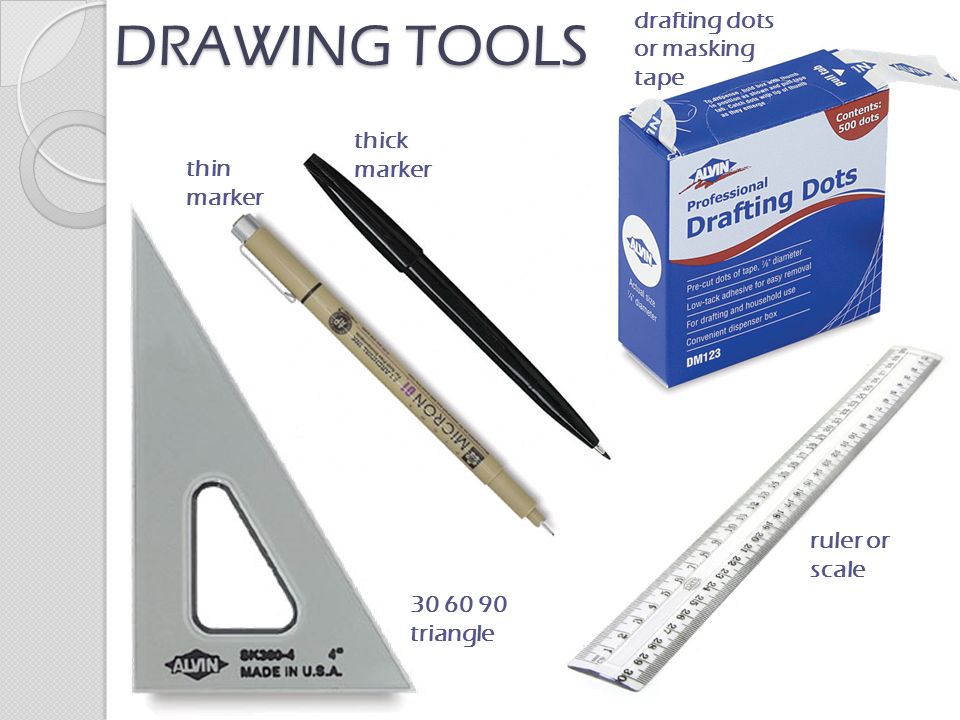
Bring your markers and pencil and move to one of the large tables in Pappalardo.
connect the matching letters and symbols without lifting your marker, draw from your shoulders, not your wrist – STAND UP to the side – try drawing a few circles without lifting your marker. try inscribing some circles in the squares you’ve just created. can you make the circle touch the center of each side of the square can you do it without lifting your pen try inscribing ovals in the three orientations of diamonds created by two of your neighboring triangles. can you make the oval touch the center of each side of the diamond
Think about. What (subject) Who (audience) USEFULL: assembly, machining, fabrication, NOT SO USEFULL: quick idea generation, or communication of rough concepts.
Technical Drawing - Isometric
Technical Drawing – Orthographic
Technical Drawing – Assembly section
Technical Drawing – More Sections
bottom edges slant up at a 30 degree angle from horizontal. (You should be viewing 3 of the 6 faces of a cube) 30° 30°
width and depth ( horizontal ) lines are drawn 30 degrees from the horizontal at their true (or scaled) length. all lines parallel to the height, width or depth are at their true (or scaled) length. lines not parallel to these axes are not drawn at their true length. height. width. depth.
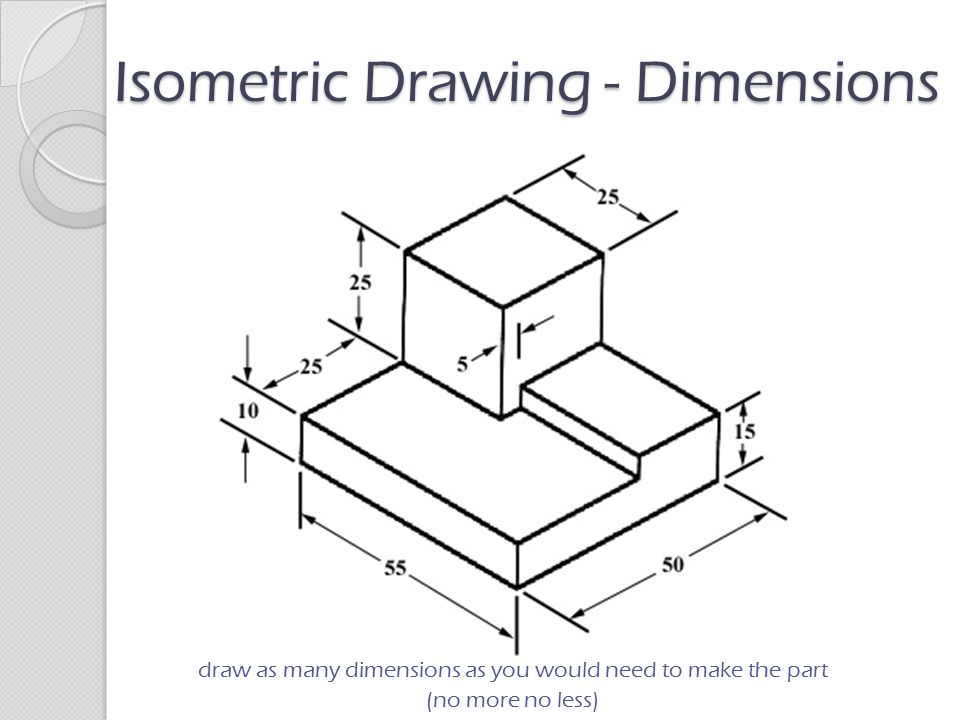
Isometric Drawing - Dimensions
Identify line to dimension.
draw as many dimensions as you would need to make the part. (no more no less)
Time to draw!!!!!! Take all your drawing tools and move to the tables in pappalardo.
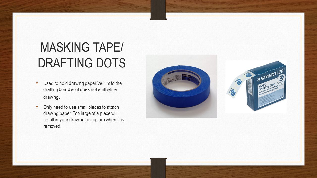
1 – draw a single vertical (centered, starting at the bottom) 2 – draw the depth and width of the cube from the bottom of the vertical (30 degrees to the horizontal) 3 – draw the other two verticals. 4 – draw the top of the cube. trace over your cube freehand with your thin marker. affix isometric graph paper to work space with draft dots. cover with trace. I will do on the board as they do on their page.
draw a rectangular prism (use pencil and a ruler at first) 1 – use any height, width and depth – same steps as the cube. 2 – lightly trace the hidden lines of the bottom plane. 3 – draw the L on the bottom and top plane, with the negative space closest to you. 4 – fill in the remaining verticals. 5 – erase extra lines. trace over your lines with the thin marker, then trace around the outermost edges of your shape with the thick marker. cover with fresh trace. I will do on the board as they do on their page.
inscribe circles on each face of the cube. 1 – in pencil, lightly divide each face into four equal sections by connecting the opposite edge midpoints. 2 – (in marker) draw arcs in each of the four sections, connecting the midpoints of each edge and creating three inscribed circles. reaffix cube trace. I will do on the board as they do on their page.
draw one of the shapes in pencil at 1:2 scale. you will need to measure the shape. pick the appropriate orientation – the one that gives the most detail about the object and its features. start with a cube. remember – vertical lines, or lines in horizontal planes should be drawn first, then other lines (which may not be true length) can be drawn last to connect appropriate edges. trace over your object with your thin marker, then trace around the outermost edges of your object with the thick marker. hand out shapes. I will walk around and see how they’re doing. at the end I will ask who couldn’t fully express their shape with isometric this will lead into orthographic.
did anyone have an object that couldn’t be fully expressed with a single isometric drawing
what is the minimum number of views required to capture every object feature often the answer is three, but it could be less or more! what is the best way to lay out these drawings. best use of paper, should drawings be scaled up or down we will be dimensioning drawings, so leave enough space around each view to add dimensions. think about the order of inking to avoid smudging.
thick continuous line – used for visible edges and outlines. thin continuous line – hatching, short center lines, dimensions or projection lines. thin dash-dot line – center lines, to identify the center of a circle or a line of symmetry. thin dashed line – used for important hidden detail, such a hole in a solid or a wall thickness.
draw as many dimensions as you would need to make the part, no more, no less. do not add redundant dimensions, will lead to conflicts with tolerances – if you can deduce a dimension from other displayed dimensions, it is redundant. often better to continually measure from one point than measuring from one point to another.
dimensioning circles – all dimensions proceeded by Ø – note use of center lines. two projected lines from a diameter (least used) internally along the diameter, labeled internally or externally, depending on size. if circle is very small, can dimension from outside the circle using an arrow which points towards the center. dimensioning radii – all dimensions proceeded by R – should only have one arrowhead, and arrow should pass through circle center. can locate the center of the circle with center lines and an arrow with the measurement outside the circle. can dimension with an arrow originating from the center without center lines, label at center of circle.
all of your drawings should include: title of part. your name. date of drawing. version (if a previous drawing of the part exists) scale (dimensions will always be represented as if the drawing is 1:1, actual size) 1:1 – actual size. 2:1 – drawing is twice as big as object. 1:2 – drawing is half as big as object. a few words about dimensions. all measurements are in mm – we’ll do this. all measurements are in inches. these should be written neatly on the drawing sheet, each item is usually surrounded by a thin box, and the items are generally adjacent – like a table.
Time to Draw Take all your drawing materials and move back to Pappalardo.
try drawing your 3D L with the orthographic technique. affix real paper with drafting dots.
try drawing one of the ten objects with the orthographic technique. will need to measure the object. can use ruler and pencil at first. trace over lines with appropriate marker. write scale and other page layout items on your drawing. don’t forget to dimension your drawing! affix real paper with drafting dots.
draw something from your life at WTP, later you’ll model it in SolidWorks and create the isometric and orthographic drawings from the 3D model – use trace. isometric. orthographic with dimensions and proper layout. examples from other years. phones, cameras, etc. fun challenge: try drawing an object or two using only your thin and thick pens, without a ruler, pencil, straightedge or triangle – see how close to isometric you can get freehand – in your design notebook. using a pen to sketch is important because you can’t erase. cultivating this skill will teach you to draw only the lines that you really mean to draw. you should never erase your ideas – design is an iterative process, and sketches show the progression of your design – and you may be able to use ideas or elements from earlier designs.
use the skills from dimensioning everything else. diameter symbol. as many views as required to fully understand hole. center lines and symmetry lines.
often interior features can not be fully described by isometric and orthographic drawings – rather than struggling with hidden lines, a section may be more easy to create and more easy to understand’ imagine slicing the object along a plane. don’t forget line weights and centerlines. hatch material that is touching the slice plane. label orthographic drawing A-A (or B-B) to show where the slice was taken. orthographic sections are much more common than isometric sections.
Use sketching for general design, planning and idea sharing. Look and feel. Form. process. Use technical drawing for final details such as assembly or part drawings for fabrication. Isometric. Orthographic. Assembly. SKETCHING. FORM – where do I place my grabber arm, ballast. PROCESS – water sampler, what are the steps, final collaboration what are the steps to recover cargo, sunken ship
words are pretty effective for some situations, often in Engineering and design, pictures are much more effective. Importance of communication. - what’s your idea worth if you cant share it with others. In the real world you have to collaborate, so you need to know how to communicate your ideas or they are not very useful to you.
No one is an expert at everything, so we must collaborate to reach a common goal. Picture is worth a 1000 words!!! words are pretty effective for some situations, often in Engineering and design, pictures are much more effective. Importance of communication. - what’s your idea worth if you cant share it with others. In the real world you have to collaborate, so you need to know how to communicate your ideas or they are not very useful to you.
Subject – what you are trying to convey (Process, structure, function, material, etc….) Audience – who you are communicating with (designer, client, manager, public, other engineers) Two important things to think about when drawing.
Drawing types we will explore today. Sketches. Isometric Drawings. Orthographic Projections.
USEFULL: Idea sharing / working out low level details / idea generating. NOT SO USEFULL: PART MANUFACTURE OR ASSEMBLE.
Sketching – look and feel
Sketching – to show process
Sketching usually associated with look and feel, try and emphasize that other models are at times effective. EX (restaurant floor plan)
Bring your markers and pencil and move to one of the large tables in Pappalardo.
connect the matching letters and symbols without lifting your marker, draw from your shoulders, not your wrist – STAND UP to the side – try drawing a few circles without lifting your marker. try inscribing some circles in the squares you’ve just created. can you make the circle touch the center of each side of the square can you do it without lifting your pen try inscribing ovals in the three orientations of diamonds created by two of your neighboring triangles. can you make the oval touch the center of each side of the diamond
Think about. What (subject) Who (audience) USEFULL: assembly, machining, fabrication, NOT SO USEFULL: quick idea generation, or communication of rough concepts.
Technical Drawing - Isometric
Technical Drawing – Orthographic
Technical Drawing – Assembly section
Technical Drawing – More Sections
bottom edges slant up at a 30 degree angle from horizontal. (You should be viewing 3 of the 6 faces of a cube) 30° 30°
width and depth ( horizontal ) lines are drawn 30 degrees from the horizontal at their true (or scaled) length. all lines parallel to the height, width or depth are at their true (or scaled) length. lines not parallel to these axes are not drawn at their true length. height. width. depth.
Isometric Drawing - Dimensions
Identify line to dimension.
draw as many dimensions as you would need to make the part. (no more no less)
Time to draw!!!!!! Take all your drawing tools and move to the tables in pappalardo.
1 – draw a single vertical (centered, starting at the bottom) 2 – draw the depth and width of the cube from the bottom of the vertical (30 degrees to the horizontal) 3 – draw the other two verticals. 4 – draw the top of the cube. trace over your cube freehand with your thin marker. affix isometric graph paper to work space with draft dots. cover with trace. I will do on the board as they do on their page.
draw a rectangular prism (use pencil and a ruler at first) 1 – use any height, width and depth – same steps as the cube. 2 – lightly trace the hidden lines of the bottom plane. 3 – draw the L on the bottom and top plane, with the negative space closest to you. 4 – fill in the remaining verticals. 5 – erase extra lines. trace over your lines with the thin marker, then trace around the outermost edges of your shape with the thick marker. cover with fresh trace. I will do on the board as they do on their page.
inscribe circles on each face of the cube. 1 – in pencil, lightly divide each face into four equal sections by connecting the opposite edge midpoints. 2 – (in marker) draw arcs in each of the four sections, connecting the midpoints of each edge and creating three inscribed circles. reaffix cube trace. I will do on the board as they do on their page.
draw one of the shapes in pencil at 1:2 scale. you will need to measure the shape. pick the appropriate orientation – the one that gives the most detail about the object and its features. start with a cube. remember – vertical lines, or lines in horizontal planes should be drawn first, then other lines (which may not be true length) can be drawn last to connect appropriate edges. trace over your object with your thin marker, then trace around the outermost edges of your object with the thick marker. hand out shapes. I will walk around and see how they’re doing. at the end I will ask who couldn’t fully express their shape with isometric this will lead into orthographic.
did anyone have an object that couldn’t be fully expressed with a single isometric drawing
what is the minimum number of views required to capture every object feature often the answer is three, but it could be less or more! what is the best way to lay out these drawings. best use of paper, should drawings be scaled up or down we will be dimensioning drawings, so leave enough space around each view to add dimensions. think about the order of inking to avoid smudging.
thick continuous line – used for visible edges and outlines. thin continuous line – hatching, short center lines, dimensions or projection lines. thin dash-dot line – center lines, to identify the center of a circle or a line of symmetry. thin dashed line – used for important hidden detail, such a hole in a solid or a wall thickness.
draw as many dimensions as you would need to make the part, no more, no less. do not add redundant dimensions, will lead to conflicts with tolerances – if you can deduce a dimension from other displayed dimensions, it is redundant. often better to continually measure from one point than measuring from one point to another.
dimensioning circles – all dimensions proceeded by Ø – note use of center lines. two projected lines from a diameter (least used) internally along the diameter, labeled internally or externally, depending on size. if circle is very small, can dimension from outside the circle using an arrow which points towards the center. dimensioning radii – all dimensions proceeded by R – should only have one arrowhead, and arrow should pass through circle center. can locate the center of the circle with center lines and an arrow with the measurement outside the circle. can dimension with an arrow originating from the center without center lines, label at center of circle.
all of your drawings should include: title of part. your name. date of drawing. version (if a previous drawing of the part exists) scale (dimensions will always be represented as if the drawing is 1:1, actual size) 1:1 – actual size. 2:1 – drawing is twice as big as object. 1:2 – drawing is half as big as object. a few words about dimensions. all measurements are in mm – we’ll do this. all measurements are in inches. these should be written neatly on the drawing sheet, each item is usually surrounded by a thin box, and the items are generally adjacent – like a table.
Time to Draw Take all your drawing materials and move back to Pappalardo.
try drawing your 3D L with the orthographic technique. affix real paper with drafting dots.
try drawing one of the ten objects with the orthographic technique. will need to measure the object. can use ruler and pencil at first. trace over lines with appropriate marker. write scale and other page layout items on your drawing. don’t forget to dimension your drawing! affix real paper with drafting dots.
draw something from your life at WTP, later you’ll model it in SolidWorks and create the isometric and orthographic drawings from the 3D model – use trace. isometric. orthographic with dimensions and proper layout. examples from other years. phones, cameras, etc. fun challenge: try drawing an object or two using only your thin and thick pens, without a ruler, pencil, straightedge or triangle – see how close to isometric you can get freehand – in your design notebook. using a pen to sketch is important because you can’t erase. cultivating this skill will teach you to draw only the lines that you really mean to draw. you should never erase your ideas – design is an iterative process, and sketches show the progression of your design – and you may be able to use ideas or elements from earlier designs.
use the skills from dimensioning everything else. diameter symbol. as many views as required to fully understand hole. center lines and symmetry lines.
often interior features can not be fully described by isometric and orthographic drawings – rather than struggling with hidden lines, a section may be more easy to create and more easy to understand’ imagine slicing the object along a plane. don’t forget line weights and centerlines. hatch material that is touching the slice plane. label orthographic drawing A-A (or B-B) to show where the slice was taken. orthographic sections are much more common than isometric sections.
Use sketching for general design, planning and idea sharing. Look and feel. Form. process. Use technical drawing for final details such as assembly or part drawings for fabrication. Isometric. Orthographic. Assembly. SKETCHING. FORM – where do I place my grabber arm, ballast. PROCESS – water sampler, what are the steps, final collaboration what are the steps to recover cargo, sunken ship
Google Slides Download Free - Design Drawing and Pen

Using the Drawing Tools and Format Features in PowerPoint - Video
Machine drawing
Design and Working Drawings - ppt download

Free Industry Powerpoint Templates Design
MECHANICAL DRAWING. - ppt download

GE 121 – Engineering Design - 2009 Engineering Design GE121
Engineering Drawing basics.ppt
PPT - Engineering Drawing PowerPoint Presentation, free download

40 Best Engineering Drawing Tools-Themed Templates for PowerPoint
Download Mechanical Engineering Drawing PDF
MECHANICAL DRAWING. - ppt download
Mechanical Engineering Assembly Drawing Examples And Solutions

Mechanical Engineering PowerPoint Template by PoweredTemplate.com
Technology Background png download - 815*760 - Free Transparent
Recommended for you
-
 Alvin Drafting Dots19 May 2024
 -
 Mr. Pen- Professional Drafting Dots, 500 Pieces Drafting Dots, Art19 May 2024
 -
 DRAFTING DICTIONARY AN EXPLANATION OF PRECISION DRAWING EQUIPMENT19 May 2024
 -
 Drafting A Floor Plan - ANG and JOEY19 May 2024
 -
 Pacific Arc Professional Blank Drafting Dots 7/819 May 2024
 -
 Mr. Pen- Professional Drafting Dots, 500 Pieces Drafting Dots, Art Tape, Tape Dots, Artist Masking Tape, Drafting Supplies, Architectural Dots Tape, Stationary Tape, Tape for Art and Drawing Paper : Mr. Pen: Office Products19 May 2024
 -
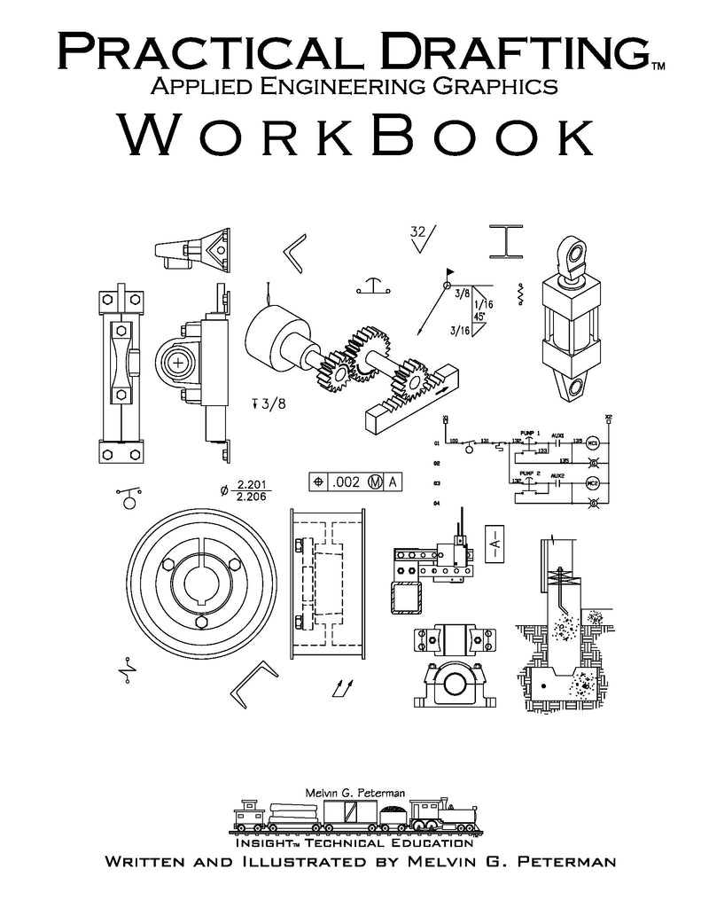 Practical Drafting™ Applied Engineering Graphics Workbook Digital Down – Insight Technical Education19 May 2024
 -
 Drafting Dots 500Ct Tulane University Official Bookstore19 May 2024
 -
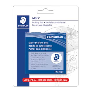
 Staedtler Drafting Dots19 May 2024
 -
 2 Pack Pacific Arc Professional Blank Drafting Dots 719 May 2024
You may also like
-
 Giantree 100pcs T Shape Pins, 2 Sizes Metal T Pins for Wigs Wig Pins for Foam Head T Pins for Sewing Wig T Pins Blocking Pins T Pins for Office Wall19 May 2024
 -
 Exclusive Offer: Get Pro Features @ 90% Discounted Price19 May 2024
 -
 Clobeau Magnifying Glasses 8x 15X 23x Magnifier LED Headband Glass Eye Magnifying Repair Tool Watchmaking Coin Stamp Currency Book Errors Jewelry Neck19 May 2024
 -
 Cutaway card with hello and flowers19 May 2024
 -
 1 x Brand New Scettar Pack of 2 plant ties, 10 mm x 20 m 12 mm x 20 m Velcro fastener tape, resealable plant Velcro tape, plant ties, plant tape for19 May 2024
 -
 Flower Bikers Patch Iron on Patches Bulk for Clothing Accessories19 May 2024
 -
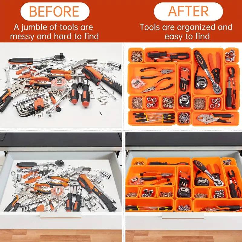 Tool Box Organizer Tool Tray Dividers, Toolbox Drawer Organizers19 May 2024
 -
 Tamiya 40ML highlighting Panel Line Accent Color 87131-87210 for19 May 2024
 -
 BIC Gel-ocity Stic Gel Pens, Medium Point, 0.7 mm, Clear Barrel, Assorted Ink, Pack of 14 Pens19 May 2024
 -
 Double Wedding Ring Quilt - Jenny's Sewing Studio19 May 2024